 NASA’s Curiosity rover is just awesome. I wanted one in my life, and so set about thinking and building… To what extent could I construct a similar robot using bits and pieces available to mortal men? I’m not interested in sampling rocks or seeking out evidence of extraterrestrial activity just yet, and so I boiled my desires down to simple remote control with a video feed – It’d be awesome fun to trundle around my house with a telepresence droid, from anywhere in the world, much like NASA are able to host a remote human presence on a planet 225 million kilometers away.
Planning
Acknowledging that such a construction was not exactly an insignificant undertaking, I spent some time in project manager mode considering my approach. I settled on assembling my droid as a series of independent engineering work ‘streams’, that when brought together, would result in the main goal: an internet controlled Remote Operated Vehicle (ROV).
Core: The project involves a computer that is connected to the internet, which can receive commands and tell motors to move on demand. The computer has a camera attached, and it is able to present the video stream via the internet.
I planned to use a Raspberry Pi as my onboard computer. This little hackable Linux machine certainly has low power requirements, and I’ve seen some impressive things done with it, including numerous projects involving cameras and motors. The Raspberry Pi is not such a great candidate for controlling any motors directly from its GPIO pins though (motors need to draw a lot of current – the tiny computer is built for very low current logic output).
In a biological system, it’s typical for a motor intention (e.g. ‘move my arm in this way’) to pass from a relatively complex ‘high level’, down through successively simpler layers of control, and finally into mechanical affectors: the brain controls muscles via the motor cortex, for instance. I thought that this methodology would be a great way to get my Raspberry Pi communicating with physical reality – by pushing commands to a ‘low level’ motor controller – for my purposes an Arduino microcontroller. But what’s the best way to get a message from the Pi into the Arduino? I established (‘forked’) a project stream: Bridge, which was intended to solve this.
Setting up a web camera on the Raspberry Pi was a critically important task, so I gave it a stream title: Eye. Similarly, internet connectivity is an essential work module (connectivity is not provided ‘out of the box’ with the RPi), and so another stream was forked: Uplink, which was to establish WiFi internet connectivity.
Vessel: I’d need to build a scaffold to hold everything together, with wheels to form a mobile platform. It’ll need a drive system with sufficient torque to deal with basic obstacles (carpet/hard floor transitions), and stay put when not driving.
Juice: There are energy requirements that must be met – a battery or batteries sufficient for both motor control and core computer power.
Soul: In order to animate the whole thing, I’d need to do some software development in a couple of sub work-streams. Firstly I’d have to present a control interface to the user (me at a remote machine), so that I could send commands to some process running on the robot ‘host’ computer. This should then push commands onto its motor control layer, to ultimately translate my control intentions into motor actions.
Production
It’s cool to think that if I were ‘in industry’, I could farm out each stream to a resource or team to develop – that’d allow the production of something really big and cool within an efficient time; just like at NASA! However I was tackling my project alone (kind of, as you’ll see), and so worked through each stream one after the other, switching to progress upon a different task whenever I got stuck or bored. What follows is a debrief of each work stream – hopefully some of the things I learned will assist others looking to achieve similar goals.
Uplink – Raspberry Pi WiFi Connectivity
After a bit of internet research targeting ‘cheap wifi dongle for Raspberry Pi’, I hoped to follow the success of others with the Edimax 7811un WiFi dongle. Unfortunately for me and my year out of date Raspbian Linux distro, this did not at all work with prebuilt driver modules helpfully posted by others on the web. Not fully confident with building from source for my distro (as a Linux noob), I tried to get the prebuilt drivers working with an updated Raspbian distro. Failed again – now the distro was too new for the drivers! I then tried an entirely different OS: Arch Linux, hoping the device would work immediately with included drivers, but was totally put off by the different command environment (I’m really am a Linux noob). I finally tried Occidentalis 0.2 (based on familiar Raspbian, and with a lot of hobbyist-centric modules preloaded); after some very simple configuration, the Edimax now worked ‘out of the box’!
This was a difficult project stream for me, since it involved a lot of learning about Linux hardware compatibility and setup – the entire Linux hardware configuration process seems so arbitrary; options are littered about various obscure places on the core file system, and little sensible help aimed at newcomers (who want to understand the process and not just copy some commands) can be found on the web. Occidentalis came ‘pre-baked’ and ready to go, a perfectly simple solution to wireless internetting on the RPi, with a dirt cheap WiFi dongle.
Eye – webcamera streaming with Raspberry Pi
 Similar problems to those experienced with Uplink were encountered whilst setting up the webcam (the lesson: Linux hardware setup is a pain). The main issue was trying to get a Linux distro that supported both the Edimax dongle for WiFi and my webcamera (a Microsoft Lifecam 3000). Occidentalis 0.2 totally saved the day with support for my camera already built in, and my camera hardware was ready to use. I also tried a really cheap camera, the Microsoft XBox Live Vision (around a fiver including postage via Amazon), and this worked beautifully too, with no setup required! I found this hardware compatibility resource particularly useful whilst shopping for suitable hardware: http://elinux.org/RPi_VerifiedPeripherals
Actually streaming the video from my functional camera turned out to be a mammoth research and development endeavour – I tried various systems designed to stream a camera feed to the internet with no success; the popular programs ffserver, avserver and motion all failed at various points during investigation, each with obscure errors. I was running out of patience after days getting nowhere, until I happily stumbled upon mjpg-streamer (installed from the command line like other Linux programs using apt-get) – it worked immediately, and it worked so very well. Furthermore, the video stream format hosted by this program was ready to drop straight into a webpage, which is perfect for my requirements – rather than writing a ‘native’ desktop program to control the robot remotely, I’d simply be able to use a web page to build my control interface: much simpler.
Bridge – communication from Raspberry Pi to Arduino
There turn out to be many numerous methods of getting a computer to talk to another bit of hardware: Serial, I2C etc. I wanted a quick and easy solution, so opted for basic digital logic output directly through the Raspberry Pi’s general purpose input/output pins. I can define my motor control intentions in terms of binary states, and by setting the logic voltage of the pins high for 1 and low for 0, I can push the control intention to my Arduino:
Each motor has three states, which can be described by two bits; a ‘drive’ bit and a ‘reverse’ bit.
idle: 00 (both ‘drive’ and ‘reverse’ bits zero)
driving forwards: 01 (reverse bit 0, drive bit 1)
driving backwards: 11 (reverse bit 1, drive bit 1)
…which means that I need just four bits to control two motors according to the following:
idle – both motors stationary: 0000
driving forwards – both motors turning forwards: 0101
driving backwards – both motors turning backwards: 1111
turning left – left motor turning backwards, right motor forwards: 1101
turning right – right motor turning backwards, left motor forwards: 0111
Further consideration reveals that up to 7 digital states can actually be controlled by just three bits (freeing up one pin from the scheme above), but I eventually stuck with keeping things simple and obvious, using four bits according to the scheme above.
The voltage output from the Raspberry Pi is 3.3V, whilst the voltage expected by the Arduino inputs is 5V – whilst it’s possible to connect directly from Pi into Arduino (3.3V reads perfectly well as a logic 1 – the ‘high’ threshold on Arduino is closer to 2.8V by my experiences), I wanted to ‘do things properly’ with a logic buffer. I tried pushing my bits from the RPi to a 74HCT541 Octal buffer IC, with 5V on the Arduino side. Using the chip to ‘drive’ inputs to the Arduino worked okay until a fourth ‘high’ output was demanded from it – there seemed to be a voltage drop associated with each high output, and by setting all four bits to on (1111), the informational state was very unstable, with ‘high’ represented by slightly less than 2.8V on the Arduino side on each pin. A conversation with a seasoned industrial engineer (thanks dad!) introduced me to the difference between ‘source’ and ‘sink’ drive, as it pertains to IC circuits. I had assumed that ‘source’ mode was how every IC worked! A quick bit of prototyping using a ‘sink’ setup to drive four LEDs worked much better than a source drive arrangement; logic voltage could be made to remain consistent with each additional high output from the octal buffer, but I just couldn’t figure out how to drive my Arduino inputs in this way – ‘pulling’ current from the arduino to represent a logic 1 (I’m also an electronics newbie – though in retrospect I’m sure this could be done with a PNP transistor arrangement).
I ditched the IC and tried an entirely different approach using plain old transistors to translate my Raspberry Pi output voltage from 3.3 to 5v, and experienced a voltage drop across the transistor leading to my 5v dropping to below 2.8v (regardless of swapping out resistors, changing transistor types etc.) – again no good!
Given all the electronics grief thus far, I ended up just plugging RPi into Arduino (sometimes the simplest solutions are the best), acknowledging that this is perfectly safe as my Arduino on the connected pins is in input mode – it won’t be dropping 5v onto the RPi anytime soon. I also noted that I seriously need to spend more time working with electronics to understand what caused my numerous issues during this work stream.
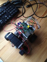 Vessel – a simple wheeled robot body
Possibly the easiest task of all: have some fun with Meccano (a great modular construction system with enough robustness for light robot application). I looked into the possibility of adding tank tracks (a belt sander reel cut in half lengthways) but this didn’t work out how I intended – I preferred a smaller frame than dictated by the size of the belt, so wheels it was.
By modifying a couple of servo motors so that they rotated continuously in either direction (rather than the fixed angle default), I had some high torque drive units, with easy control using the pulse width modulation output from the Arduino.
Juice – Power supply for Pi and motors
Whilst browsing the discounted goods aisle in Maplin, I found a 9000MAh rechargeable power pack with USB output, intended as a supplementary charging source for mobile devices. It’s pretty heavy, but this battery had a massive capacity! A first trial with my WiFi connected Raspberry Pi powered by this little brick proved that it could idle the Pi happily for fourteen hours.
My drive servos require a good bit of power however (servos needing typically 6v, and a fair bit of current) – I didn’t want to put too great a demand on my new power source, and so though it’d do well as my CPU power source for both the Arduino and Raspberry Pi. I’d use a separate source of 4 AA batteries (~6v) to drive my motors.
I built a small ‘power station’ circuit to allow me to source power from each supply, with a common ground rail connected to the rest of the robot circuitry by a master on/off switch. I learned a core lesson in electronics at this point: different battery voltages can happily be combined so long as their grounds are connected – I once couldn’t comprehend how this was possible without one battery ‘leaking’ charge into the other, thus leaving the batteries ‘unbalanced’. Such a thing just doesn’t happen – for charge to enter a battery at one end, an equal but opposite charge must leave at the other end, and so connecting multiple batteries to a common ground simply completes a pathway for charge from each to complete its circuit – there’s no adverse effect with ‘excess’ charge crossing from one battery to the other; a simple fact, but fundamental to my growing practical understanding.
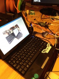
Soul – Programming a telepresence ‘droid
As a software developer by trade I’m on familiar ground here. A bit of research into how the Raspberry Pi’s GPIO pins could be controlled via the internet led me to discover a set of interconnected software elements called WebIOPi – an *amazing* bit of work by a single person; not only did this software fulfill my requirements almost immediately all the way from front end control interface all the way to GPIO action on the Pi, but the author (blog linked here) was in the process of writing an article for a hobbyist magazine about making a ‘cambot’ – refer to issues 9 and 10 of The Magpi; basically the same as my own project! Furthermore, he’d kindly committed his control interface source to the repository for use by anyone (with files supporting the written article also available here)… In this respect I cannot claim credit for this portion of the ‘Soul’ workstream – this turned out to have been fulfilled already by another skilled engineer – with a very few small tweaks (and donation where it’s due to the author of WebIOPi), my project requirements were met.
To summarise the architecture briefly: WebIOPi hosts a webserver on the Raspberry Pi, upon which HTML content can be accessed remotely using a web browser. On this webserver I can place a simple HTML document that uses WebIOPi’s JavaScript API to communicate with a Python script running on the Raspberry Pi; this sets the state of the GPIO pins based on commands originating from button presses on the web page. ‘Macro’ commands can be defined, and so it’s easy to define a ‘forward’ button as meaning ‘0101’ on any four GPIO pins (the intention to drive both my motors accordingly), for example.
The final portion of programming was a very simple bit of code on the Arduino. A loop monitors input on four pins connected to the GPIO from the Raspberry Pi, and sets the ‘angle’ desired by my modified servo motors accordingly, via PWM output. The angle will never be reached by my modified servos, so they’ll spin continually in one or other direction, with a speed proportional to how far the angle is defined from zero.
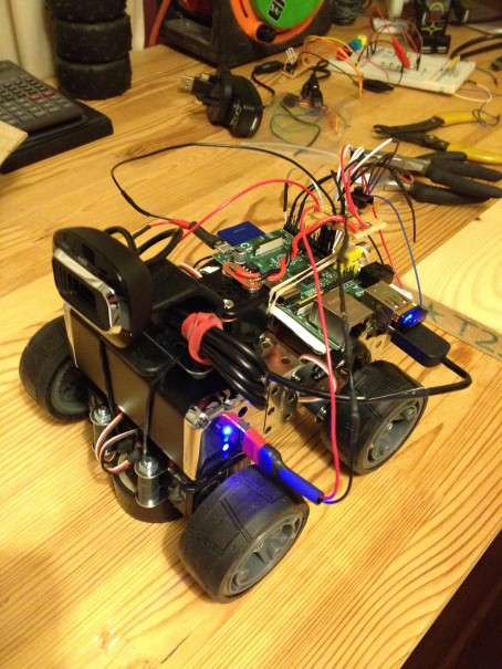
Final assembly
A bit of insulating tape to hold everything in place and it’s good to go! My robot’s name: Telemus – a cyclops from legend, and a nod towards the word ‘telemetry’! Project success; a lot of learning had during construction, and a lot of fun to be had trundling around my own local planet Mars. A video of my rover in action follows…
Project complete
The future
I’d really like to add a set of high power LEDs to ‘light up the dark places’ – the on/off state of this will easily be controlled with one GPIO pin connected to a transistor switch.
I’d also really like my robot to be able to tackle stairs! This will require both a larger body scale, and some better locomotion system than wheels – tracks might do it, but I’m highly intrigued by Boston Dynamics’ RHex robot, with its leg/wheel crossover type locomotion system…
A larger body could support a beefier power system for drive. It might be interesting to add a manipulator or arm of some kind, for basic interaction with the environment – possibly even aid with raising the front of the (tracked) robot’s body for mounting stairs.

how do you run the mjpg server and the webiopi server at a time
I wrote an executable bash script called initbot.sh; in it was the following:
sudo python cambot.py & ./streamon.sh
…where cambot.py was the python script to set up and launch the webiopi session with its macros, and streamon.sh was another script simply launching mjpeg-streamer. The important part is the the ampersand ‘&’ – it means that the commands in the shell script are executed one after another. Something else worth looking into is running webiopi and or mjpeg streamer as a daemon, that is, a background process that you can set to start up with the machine.
hello
my name is nasser and i am student in university of bahrain
before few weeks i have bought an arduino device with gsm/gps/gprs shield.
i was wondring that this device could link me with the web server , not only sending and reseving the sms through arduino gsm.
am facing some trouble with device , i need the library or the codes that i can link my device to the web server.
my project is to control an auto mobile through web site ,and the arduino gsm gprs works as reseving the commands throug the web
am also using a cam as yours , so can you help me for that or any suggation
please email me saif_bbb@hotmail.com
This may be of interest to you. http://deimos.dhrstudios.com/
I’m still building it, but it’s pretty similar
I must say, I like your explanation the best so far on these cambot’s. It helped me grasp things much better than the other ones I have read. I do have a question though, do you have an example of the arduino code you used? I’m basically doing the same thing but instead of a mobile robot, I’m using two servo motors to simply pan and tilt (up & down – Left and right). Did you simply use jumper wire to connect the pi’s gpio pins to the arduino? analog input pins?
It’s just a series of jumper leads connecting the Raspberry Pi to the Arduino, yes – though that’s only safe for Pi to Arduino communication, and quite risky; if you connect ‘high’ output pins from Arduino to Pi, you could damage the Raspberry!
Unfortunately I’ve lent the computer with the original Arduino source on to a friend, so don’t have access to that just now – I started writing some pseudocode to post instead, but I don’t think it’s all that helpful; it’s simple in principle to write a loop that sets output based on pin input – here are some useful pointers though:
– Input from Pi to Arduino is digital
– Output to servos from Arduino is hardware PWM
– How to fully stop the motors: so long as there’s output to the PWM pins, the motors will be moving, even if you have stopped inputting from the Raspberry Pi! I found that attaching the servo and detaching it (in software) when input stopped was essential. Check the reference here: http://arduino.cc/en/reference/servo – see the attach() and detach() functions – I basically call attach() when input begins and detach() when it ends – this stops the PWM signal, and the servo stops moving.
I’ll drop some code into the blog post when I get my machine back also.
Thanks for the reply. I finally got my pan and tilt working! I had a few good days of trial and error, but finally got it working. I didn’t use the attach/detach, but did try at first – but got frustrated with it. In my case, I wanted to move the pan and tilt by 10 degrees each time the user would hit the up,down or left,right. and then stay in that position so the user could look through the webcam where they wanted (believe me I was pulling my hair out at times). I did end up using the for bits like you mentioned 0101, 1010, 1001, 0110 etc.. like most of the cambot code was using. I ended up also using the python code which already used those functions and macros so I didn’t have to adjust much which was helpful. I have attached the code I ended up making below. The python code would reset to stop position (0000) when clikcking on the Left,right,up,down, so I found that if I just put a delay in the arduino code that I could get it to move 10 degrees and if you click off the button the servo would stop at that position which was really helpful (but took days to finally figure out – trial and error can be so frustrating). anyway here is my arduino code I used, I would still like to see the code you created as I like to learn from others and what they have done….
#include
Servo tilt; // create servo object to control a servo
Servo pan; // create servo object to control a servo
// a maximum of eight servo objects can be created
int pos = 0; // variable to store the servo position
int lpin1 = 2; // Arduino input pin connected to output pin on GPIO 9
int lpin2 = 4; // Arduino input pin connected to output pin on GPIO 10
int rpin1 = 8; // Arduino input pin connected to output pin on GPIO 23
int rpin2 = 7; // Arduino input pin connected to output pin on GPIO 24
//int lpin1 = 4; // Arduino input pin connected to output pin on GPIO 9
//int lpin2 = 2; // Arduino input pin connected to output pin on GPIO 10
//int rpin1 = 7; // Arduino input pin connected to output pin on GPIO 23
//int rpin2 = 8; // Arduino input pin connected to output pin on GPIO 24
int l1 ;
int l2 ;
int r1 ;
int r2 ;
int valtilt = 90; // variable to store the read value
int valpan = 90; // variable to store the read value
void setup()
{
Serial.begin(9600);
pinMode(lpin1, INPUT); // sets the digital pin as input
pinMode(lpin2, INPUT); // sets the digital pin as input
pinMode(rpin1, INPUT); // sets the digital pin as input
pinMode(rpin2, INPUT); // sets the digital pin as input
tilt.attach(9); // attaches the servo on pin 9 to the servo object
pan.attach(10); // attaches the servo on pin 10 to the servo object
tilt.write(valtilt); // positions the servo at its default location I want
pan.write(valpan); // positions the servo at its default location I want
}
void loop() {
l1=digitalRead(lpin1);
l2=digitalRead(lpin2);
r1=digitalRead(rpin1);
r2=digitalRead(rpin2);
//stopped
if (l1==0 & l2==0 & r1==0 & r2==0) {
delay(1000);
}//up (forward)
else if (l1==1 & l2==0 & r1==1 & r2==0) {
if (valtilt+10 0){
valtilt=valtilt-10;
tilt.write(valtilt);
delay(1000);
}
}//left
else if (l1==0 & l2==1 & r1==1 & r2==0) {
if (valpan +100){
valpan=valpan-10;
pan.write(valpan);
delay(1000);
}
}
}
I see it cut off the remainder of my code but you can get the idea of what was occurring 😉
I have referred to the same project and my work is pretty similar to yours. I am having a problem though. I run mjpg-streamer and webiopi together. The moment I press for pin manipulation, my mjpg server crashes.. Any idea what may be causing this??
Does it give you any meaningful error messages? Perhaps there’s an mjpeg-streamer log that will give you some useful info… Can’t think why it’d crash on key press, unless the entire raspberry pi is crashing (which could be related to your wiring to the pins)?
Funny part is there is no error message. I haven’t checked the mjpg streamer log though. My Pi and webcam both were being powered by a USB Hub and a WiFi dongle was attached to Pi directly. Can the problem be in power supply? Since I use the 5V pin and the Ground pin to power up a relay board for my motor control and use the other GPIO pins for my sending signals to the relay board.
Ha! Yes totally! That does have the hallmarks of low power weirdness now you mention it. Definitely try a different power supply, or don’t use a keyboard and ‘remote in’ to control your pi with ConnectBot (Android app) if you can.
Or better yet, power the ‘load’ (relay, you say) from another source. Just remember to make all the grounds common, like I mention in the post.
So do you think getting my WiFi dongle on the Hub will help? That will relieve the Pi of the supply needed for WiFi. And maybe use AA batteries to power up the relay board.
Yes indeed, so long as the hub has its own power supply
That worked perfectly! The mjpg streamer and webiopi server keep running.. Thanks a ton!
😀 nice work
[…] As Arduino embraces Linux — albeit at arm’s length — robot projects are increasingly combining the two platforms, typically using the Raspberry Pi as the Linux computer. Hybrid Pi/Arduino robot projects include the Ardux Robot, the Arduino/Pi Robot, and the Telemus. […]